The Role of Simulation in Next-Gen Wiring Diagram Tools
XTEN-AV has always been at the forefront of delivering advanced tools that empower engineers, designers, and AV professionals to work smarter and faster. One of the most transformative features in modern electrical design is simulation within Wiring Diagram Software. Simulation allows designers to test, verify, and optimize complex electrical circuits before any physical installation takes place. This capability is reshaping the way professionals approach electrical planning, troubleshooting, and education, making projects safer, faster, and more efficient.
In this blog, we will explore the importance of simulation in next-generation Wiring Diagram Software, its benefits, key functionalities, and best practices for leveraging these tools effectively.
Introduction to Simulation in Wiring Design
Simulation is the process of creating a virtual model of an electrical system to predict its behavior under different conditions. In the past, engineers relied heavily on manual calculations, prototypes, and trial-and-error methods. These approaches were time-consuming, prone to errors, and often expensive.
Modern Wiring Diagram Software changes the game by integrating simulation directly into the design workflow. Designers can now visualize current flow, test circuit logic, and detect potential issues without touching a single wire. This capability is especially important for complex projects such as smart buildings, industrial automation, and next-generation AV systems.
Why Simulation Matters
The role of simulation in electrical design cannot be overstated. Here are some of the key reasons why simulation is indispensable in modern Wiring Diagram Software:
-
Error Prevention
Simulation allows engineers to detect design flaws such as short circuits, incorrect connections, or overloaded circuits before they cause real-world problems. -
Time and Cost Savings
By testing virtually, projects can avoid costly rework or delays caused by physical prototyping and installation errors. -
Enhanced Design Accuracy
Designers can validate that all components function as intended, ensuring the final installation meets performance specifications. -
Improved Safety
Simulating electrical faults and overloads helps identify potential hazards, reducing the risk of accidents during installation. -
Optimization
Engineers can experiment with different layouts, wiring paths, and component configurations to achieve the most efficient design.
Key Features of Simulation in Next-Gen Wiring Diagram Tools
Modern Wiring Diagram Software includes a range of simulation features that make it a powerful tool for professionals.
1. Real-Time Circuit Analysis
Simulation tools can display current, voltage, and resistance in real time. This feature enables designers to understand how their circuits will behave under various load conditions. For example, in an AV system installation, engineers can see if signal lines are properly balanced and if power distribution meets requirements.
2. Fault Detection
Next-generation software can simulate potential failures such as short circuits, open circuits, or component malfunctions. The software highlights the problematic areas, allowing engineers to fix issues before physical deployment.
3. Scenario Testing
Simulation allows users to test circuits under different scenarios. Engineers can simulate peak loads, equipment failure, or unusual environmental conditions to evaluate system resilience. This is especially valuable in industrial and commercial installations where downtime can be costly.
4. Integration with Other Tools
Advanced Wiring Diagram Software often integrates with CAD tools, building management systems, and even IoT platforms. This allows simulations to account for physical layouts, communication protocols, and automation logic, creating a comprehensive digital twin of the project.
5. Educational and Training Value
Simulation is not only useful for professional engineers but also for training new technicians and students. It provides a safe environment to learn about circuit behavior, troubleshooting, and system optimization without the risk of electrical hazards.
Step-by-Step Approach to Using Simulation
To leverage simulation effectively, engineers can follow these steps in Wiring Diagram Software:
Step 1. Define the Circuit Components
Start by adding all electrical components such as switches, relays, resistors, power supplies, and sensors into the software. Accurate representation is critical for realistic simulation results.
Step 2. Connect Components Properly
Use the wiring tools to establish connections between components. Ensure that each connection reflects real-world behavior, including correct polarity and routing.
Step 3. Set Simulation Parameters
Define the parameters for the simulation, including voltage, current limits, load characteristics, and environmental factors. These settings help the software predict realistic behavior.
Step 4. Run Initial Simulations
Run the simulation to observe current flows, voltages, and system behavior. Look for warnings or errors flagged by the software, such as overloaded circuits or missing connections.
Step 5. Adjust and Optimize
Modify component values, reroute connections, or change configurations to resolve any issues. Repeat the simulation until the circuit behaves as expected.
Step 6. Test Different Scenarios
Run multiple simulations under varying conditions, such as peak load, partial failure, or environmental stress. This ensures the system is resilient and reliable under real-world conditions.
Step 7. Document Results
Most Wiring Diagram Software allows exporting simulation results, including annotated diagrams, performance charts, and fault reports. This documentation is valuable for team collaboration, client approval, and future maintenance.
Best Practices for Simulation
To get the most out of simulation in Wiring Diagram Software, consider the following best practices:
-
Use Standard Symbols and Components
Standardized components ensure accurate simulation and easier communication among team members. -
Validate Inputs
Ensure all component values, tolerances, and connections are accurate before running simulations. -
Iterate Frequently
Run multiple simulations throughout the design process to catch errors early. -
Combine with Layer Management
Organizing components into layers for power, signal, and control lines improves clarity and allows targeted simulations. -
Leverage Documentation Features
Always save annotated simulation results to create a clear record of design decisions and test outcomes.
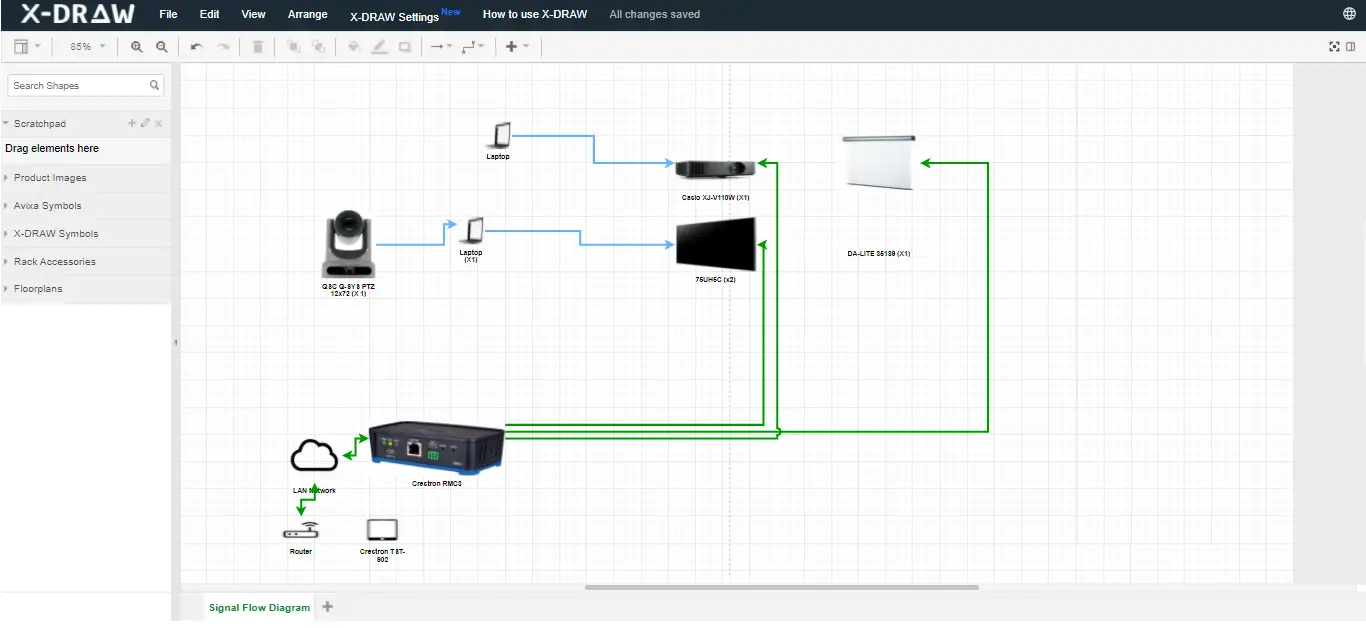
Real-World Example
Consider a modern smart conference room setup. The system includes multiple audio and video sources, motorized screens, smart lighting, and control panels. Using Wiring Diagram Software with simulation, engineers can:
-
Test if all devices receive the correct voltage.
-
Simulate peak usage when all screens and audio devices are active.
-
Detect potential faults before installation.
-
Generate documentation for the installation team.
This approach reduces installation errors, ensures reliability, and provides a clear reference for future maintenance or upgrades.
Conclusion
Simulation in next-generation Wiring Diagram Software is transforming the way engineers design, test, and implement electrical systems. By providing real-time analysis, fault detection, scenario testing, and integration capabilities, simulation improves accuracy, safety, and efficiency.
XTEN-AV empowers professionals with tools that combine intuitive design with powerful simulation features. By incorporating simulation into the workflow, engineers can ensure that complex systems perform reliably in the real world, reduce costs, and deliver professional results with confidence.
Simulation is no longer an optional feature; it is a critical component of modern electrical design, enabling smarter decisions, safer systems, and faster project completion.